The Dimension Styles button allows to manage dimension styles which are used for the current CAD file
Quick Access Panel: ![]()
Ribbon: Editor -> Text -> Dimension Styles...
Menu: Draw -> Dimension Styles...
The Dimension Styles button calls a dialog box for managing dimension styles which are used for the current CAD file.
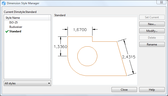
•Current Dimstyle contains the name of the current dimension style. The default dimension style is STANDARD. The current style is applied to all the new dimensions.
•Style Name contains a list of dimension styles available for the current file. The current style is highlighted. Right mouse click over the list calls a popup menu which allows selecting the current text style, renaming and deleting styles. The current style or the style in use can not be deleted.
•All styles allows managing the Style name list. Select All styles to view all the dimension styles available in the file. Select Styles in use to view only the dimension styles which are in use.
•Set current sets the selected dimension style as current.
•New allows creating your own dimension style. After you've pressed the button you will see the Create New Dimension Style dialog box appear. Enter the name of your new Dimension Style and click OK. After that you will see the Dimension Style window giving you access to adjusting the style of dimensions as it is most convenient for you.
•Modify opens the Dimension Style dialog box which contains settings for the current dimension style.
•Delete deletes the selected dimension style. Current style or a style which is in use can't be deleted.
•Rename renames the selected dimension style.
The Dialog Box Dimension Style.
The Dialog box Dimension Style contains settings for new or current dimension style:
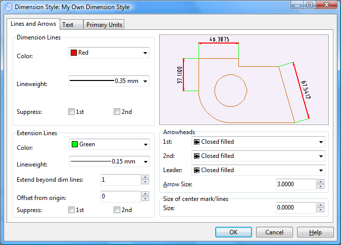
There are three available tabs:
oText
The section Dimension Lines allows defining color, line weight and the view of dimension lines. The option Suppress means here which end of a dimension line will not be shown. If you check both boxes, then the whole dimension line will be suppressed.
The section Extension Lines allows defining color, line weight and viewing order for extension lines. The option Suppress means here which end of a extension line will not be shown.
◆Extend beyond dim lines - this is the length of the part of the extension line which is above the dimension line.
◆Offset from origin - the distance between the measured element in the drawing and the extension lines.
Section Arrowheads allows defining view and size for dimension arrows, defining leader view.
Section Size of center mark/lines - defining size of marker.
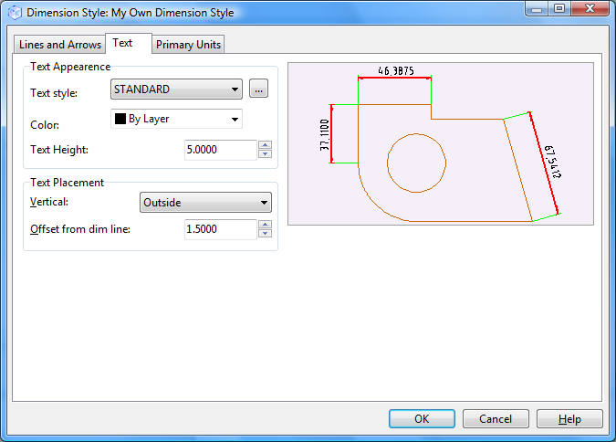 |
The Text Appearance section allows defining text style, color and height.
The section Text Placement - allows defining the position of the dimension text against the dimension and extension lines - the position can be changed along the vertical axis.
•Center - the dimension text is placed in the center between extension lines. •Above - the dimension text is over the dimension line. The distance between the dimension line and the lowest level of the dimension text is equal to the current value of Offset from Dim Line parameter. •Outside - the dimension text is placed near the extension line at the side which is most distant from the first definition point. •JIS - the dimension text is placed according to the JIS (Japanese Industrial Standards). |
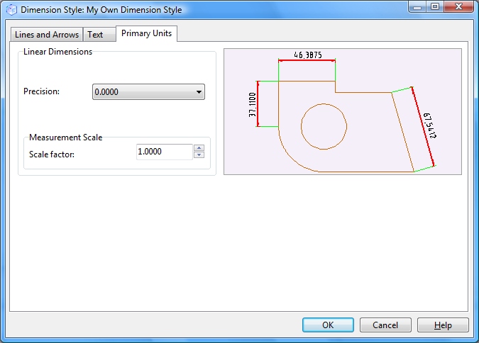 |
Linear Dimensions allows defining precision and measurement scale.
Precision defines the number of digits after comma.
Measurement Scale defines the scale parameter for linear dimensions. It is not recommended to change the default value - 1.000. For example: if this parameter is 2, then dimension 1mm will be viewed as 2mm.
Go to ABViewer